How to Test Tv Power Supply With Multimeter
In the E-book written by Kent Liew – Smart-OLED/LED/LCD TV Repair Tips – V6, chapter: "Another New Tool to easily to do the PSU self-test with monitoring feature", guides the reader on how testing can be performed on a PSU without having to connect to the TV. This test can confirm the condition of the PSU on whether it is working or it is faulty. With the knowledge gained from Jestine Yong to repair the PSU, I took on this challenge to begin the repair. I decided to repair a faulty Power Supply Unit (PSU) on hand to test the method specified in the E-Book.
I perused the web and managed to obtain the circuit diagram for the PSU as depicted in Figure A.


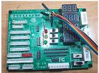
This test board as shown in Figure B, can be bought from AliExpress.
The PSU tester has built-in load resistors (3 X 5W) to simulate connection to LCD/LED TV, which will switch the PSU on if connected.
Visual checks confirmed that there were no burnt parts. When the PSU was connected to the tester, the tester did not turn on, indicating that the PSU was faulty. According to the label in the PSU output side, the stand-by volt is 5VDC marked as 5VSB (Voltage Standby). This voltage is supplied to the mainboard of the TV. Without this voltage the TV will not turn on.
Upon checking the primary supply towards Pin 1 and 3 of T401-A (Circle in RED), 330V was noted and this proof that this voltage was not boosted. This confirmed that the primary side of the PSU was working well except that the 330 VDC was not boosted. This means the PFC circuit was not working due to the missing 12 volt DC (12 VSB) from the main power supply (look at figure E). When checking the Schottky Barrier Diodes, it came to my attention that the bottom diode (D403 – Circle in ORANGE) was shorted as displayed in Figure C.

After replacing the faulty diode, the fault remained. The ring tester confirmed that the transformer is in working order (Full lights). This test was performed at pin 1 and 3 of T401-A without applying power to the PSU as shown in Figure D.

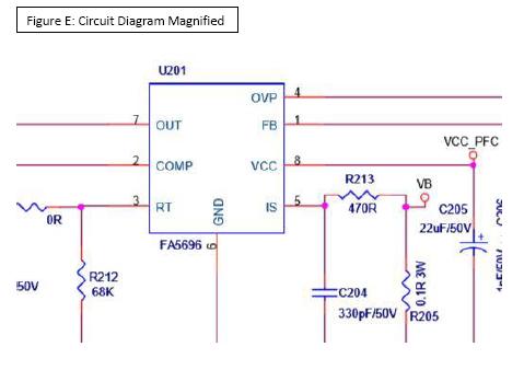
Examining the PFC circuit, I realized the PFC IC U201 pin 8 (VCC) had no voltage supply as shown in Figure E.
Following the VCC_PFC supply line, the VCC_PFC supply to U201 as portrayed in Figure F, was noted that it was coming from the below circuit:


The Drain (D) pin receiving 330 VDC steps down the voltage through built in regulation circuit (5.75 volt) and this means this IC does not need a start up resistor. This is depicted in Figure G.
Suspecting a faulty IC U401 (no switching) -figure H, I replaced the faulty LNK6767 with a LNK6777V as it was the direct substitute for LNK6767 available for replacement in the market. This replacement IC resulted in the 12 volt DC output (12 VSB) return.

However, there was still no standby voltage of 5VSB. Upon tracing the voltage lines of the DC-to-DC converting circuit, it came to my knowledge that the 5VSB is produced by IC U501 (MP1584EN), a high frequency step-down switching regulator with an integrated internal high-side high voltage power MOSFET. This can be observed in Figure I as shown below.

When probing, I realized that Pin 7 of U501 was receiving the 12VSB but there was no voltage output at pin 1. I proceeded to replace the U501 which resulted in the return of the 5VSB.
Finally, I tested the repaired board with load using the PSU tester as shown in Figure I. Connecting the repaired board to the tester showed that the PSU is fully functional.

With the guidance of Jestine Yong, I was able to complete this repair within a week, a record timing for me! I hope it was an informative read for you. Thank you for reading thus far. Do try this approach should you encounter a power supply unit without a TV for testing.

This article was prepared for you by Michael Selvam from Singapore, a 57 year old zealous electronic enthusiast. As a passionate electronic repair hobbyist, he tinkers with home entertainment systems and any faulty electronic equipment he gets his hands on. He obtained his knowledge to repair by reading books and took up the electronic courses I conducted. At present, he is employed as a Cluster Manager (Property Management) with CapitaLand and does his repair whenever time permits.
From Jestine: For your information, Michael was my training student and you can check out his training photo HERE .
Please give a support by clicking on the social buttons below. Your feedback on the post is welcome. Please leave it in the comments.
P.S-If you enjoyed reading this,click here to subscribe to my blog (free subscription).That way, you'll never miss a post. You can also forward this website link to your friends and colleagues-thanks!
You may check on his previous repair article below:
https://jestineyong.com/repair-of-philips-led-smart-tv-55pft6100-98/
Likes (83) Dislikes
 (0)
(0)
How to Test Tv Power Supply With Multimeter
Source: https://jestineyong.com/repair-and-test-of-led-tv-power-supply-board-without-connecting-to-a-tv/